
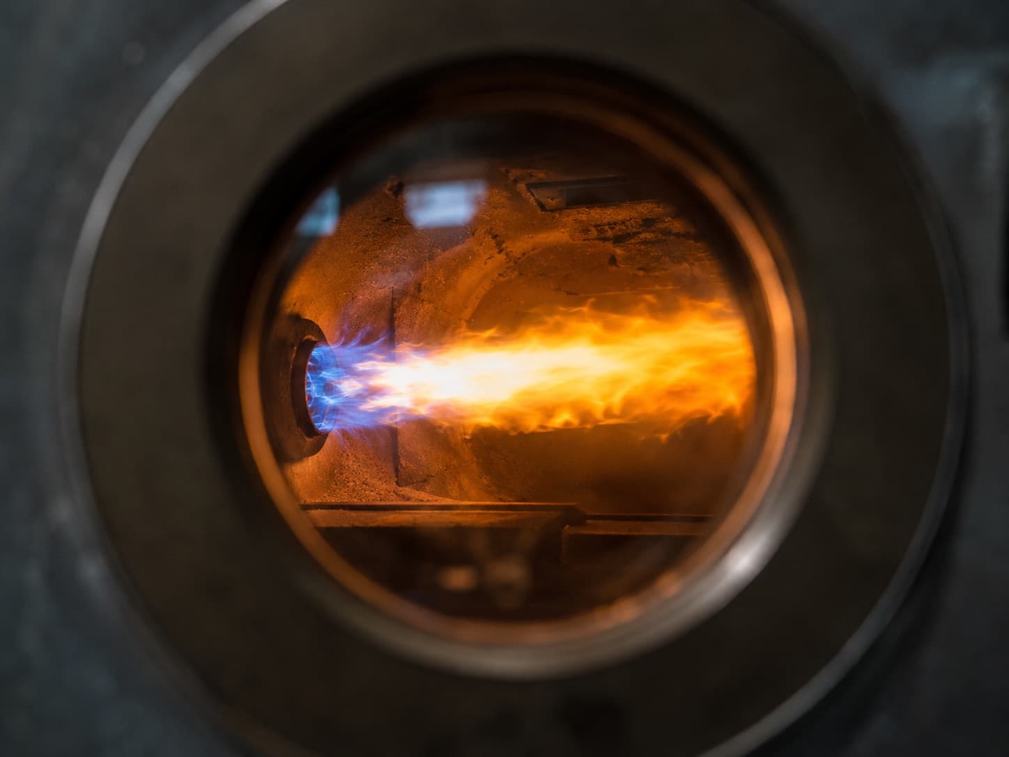
A burner is the device that mixes fuel with combustion air in a controlled ratio, ignites it, and delivers the heat output a boiler, hot-water generator or process furnace requires as a stable flame. Its job is not only ignition. By holding the fuel–air ratio at the right point, it keeps combustion safe, efficient and low in emissions. In most plants the single component that determines the annual fuel bill is not the boiler — it is how the burner is set.
What does a burner actually do?
A burner performs three functions simultaneously:
- It meters. It sets fuel flow and combustion air volume to match the current heat demand.
- It mixes and fires. It creates a turbulent fuel–air mixture and forms a stable flame in the combustion chamber.
- It supervises. It continuously monitors flame presence, air pressure and gas pressure, and cuts fuel within seconds of any deviation.
The third function is the critical one. A burner is also a safety device: the automatic supervision chain that prevents unburnt fuel from accumulating in the combustion chamber is defined by EN 676 (gas) and EN 267 (liquid fuel).
Main burner components
| Component | Function | Symptom when it fails |
|---|---|---|
| Fan and motor | Supplies combustion air | Loss of output, soot and CO |
| Air damper | Meters air volume | Fuel–air ratio drifts, efficiency drops |
| Gas train | Filter, regulator, safety shut-off valves, pressure switches | No ignition or repeated lockout |
| Fuel pump (oil) | Raises fuel to nozzle pressure | Unstable flame, increased soot |
| Nozzle / gas head | Atomises or distributes the fuel | Distorted flame shape, soot and CO |
| Ignition electrodes and transformer | Produce the ignition arc | Lockout: no flame at end of safety time |
| Ionisation probe / photocell | Detects flame presence | Lockout despite a visible flame |
| Diffuser (turbulator) | Shapes the mixture and the flame | Unstable flame, flashback risk |
| Burner control box | Manages the sequence and locks out faults | Burner will not start or locks out randomly |
The burner control box is the brain of the unit. Siemens LME/LMO/LMV, Honeywell–Satronic and Brahma families are the most widely encountered in the field. Fault codes come from this control box, not from the burner brand — see our burner fault code guide for the full breakdown.
Burner working principle: the ignition sequence step by step
A gas burner follows this sequence under EN 676. Each step depends on the successful completion of the previous one; if any condition is not met, the control box will not open the fuel valves.
- Heat demand. The boiler thermostat or steam pressure switch closes the control circuit.
- Pre-conditions checked. The control box verifies three things: the air pressure switch is in its rest position, gas pressure is above the minimum threshold, and there is no flame signal. A flame signal at this point triggers an extraneous light lockout — a safety check that often reveals a leaking valve.
- Pre-purge. The fan runs and flushes the combustion chamber and flue passes with fresh air. EN 676 requires a purge volume of at least three times the volume of the combustion chamber and flue passes, which in practice corresponds to roughly 20–30 seconds. The purpose is to expel any unburnt fuel left from the previous cycle.
- Air pressure proven. Fan pressure switches the air pressure switch over. If it does not change state, the burner locks out.
- Pre-ignition. The damper moves to ignition position and the ignition transformer strikes an arc between the electrodes.
- Safety time (TSA). The safety shut-off valves open and fuel is admitted. The flame must be established within the safety time — typically 2–3 seconds for gas burners (up to 5 seconds on small capacities; the exact value is fixed by the control box model). No flame signal in that window means fuel is cut and the unit goes to lockout.
- Flame proving. The ionisation probe exploits the conductivity of the flame to generate a DC current in the microamp range. Most control boxes require a minimum of around 1 µA; a healthy installation typically measures 4–8 µA. On oil burners a photocell (QRB) or UV cell performs this function with different thresholds — always check the control box datasheet for exact values.
- Run. Control passes to the staging or modulation system. Damper position and fuel flow track the heat demand.
- Continuous supervision. If the flame is lost during operation, the control box cuts fuel typically in under one second.
- Controlled shutdown. When demand ends, fuel is cut and the fan continues briefly for post-purge.
These ten steps are the diagnostic map for "why won't the burner fire?" The fault is always the broken link in this chain.
Types of burners
1. By fuel
| Type | Fuel | Typical application | Key consideration |
|---|---|---|---|
| Gas burner | Natural gas, LPG | Residential blocks, commercial buildings, industry | Supply pressure and gas train sizing are critical |
| Light oil burner | Gas oil / light fuel oil | Sites without gas infrastructure | Nozzle and pump pressure need regular service |
| Heavy oil burner | Heavy fuel oil | Industrial steam plants | Pre-heating and viscosity control mandatory |
| Dual-fuel burner | Gas + oil | Plants that must switch fuel on interruption | Two fuel lines and two separate combustion settings |
Dual-fuel burners are chosen by hospitals, hotels and production plants exposed to gas supply interruption. The critical point: each fuel requires its own combustion setting. A single setting cannot deliver efficient combustion on both fuels.
2. By capacity control
| Type | Operation | Turndown | Where used |
|---|---|---|---|
| Single-stage | On/off | 1:1 | Small capacities, simple plants |
| Two-stage | Low / high flame | ~1:2 | Mid-range boilers |
| Two-stage progressive | Smooth transition between stages | ~1:3 | Comfort heating plants |
| Modulating | Continuously tracks load | 1:3 – 1:10 | Steam boilers, large plants, efficiency-driven sites |
A modulating burner adjusts output continuously to match demand. By reducing on/off cycling it lowers both fuel consumption and mechanical wear, and it holds steam pressure far more steadily. With electronic ratio control (e.g. Siemens LMV5x) and O₂ trim, combustion air is corrected automatically against measured flue oxygen — which removes the efficiency drift caused by seasonal changes in air density.
3. By construction: monobloc and duoblock
- Monobloc burner: fan, motor, fuel line and control box are combined in one housing mounted directly to the boiler door. The standard solution for residential, commercial and mid-scale applications.
- Duoblock burner: the fan and fuel unit are separate from the burner body. Used on high-capacity industrial boilers and where combustion chamber back pressure is high; service access and motor selection are more flexible.
There are also atmospheric burners, which use no fan and draw combustion air by natural chimney draught. They are simple and quiet, but because the fuel–air ratio cannot be finely controlled, their efficiency and emission performance sit below forced-draught burners.
4. By mixing method
- Nozzle mix: fuel and air mix at the combustion head. Most industrial burners work this way.
- Premix: fuel and air are homogeneously mixed before entering the burner. Delivers very low NOx and wide turndown; common on condensing boilers.
Emission classes: why NOx matters
European standards classify burners by nitrogen oxide emissions:
| Standard | Class 1 | Class 2 | Class 3 |
|---|---|---|---|
| EN 676 (gas) | ≤ 170 mg/kWh | ≤ 120 mg/kWh | ≤ 80 mg/kWh |
| EN 267 (liquid fuel) | ≤ 250 mg/kWh | ≤ 185 mg/kWh | ≤ 120 mg/kWh |
Under EU Ecodesign (ErP) rules the NOx limit for gas-fired heaters up to 400 kW has been tightened to 56 mg/kWh. When specifying a new plant or replacing a burner, confirm in advance that the selected unit meets both the emission legislation applying to the site and any additional requirements from the local authority or gas distribution utility.
Turkey-specific note: industrial installations fall under the Regulation on Control of Industrial Air Pollution, while heating installations fall under the Regulation on Control of Air Pollution from Heating. Emission measurement must be carried out by an accredited laboratory where the regulation requires it.
How to select the right burner: 7 criteria
- Heat output and operating diagram. Burner capacity is never assessed against boiler output alone — it must be read together with the combustion chamber back pressure. On the manufacturer's capacity/back-pressure curve, your operating point must fall inside the envelope. This is the most common specification error we see in the field.
- Fuel type and supply pressure. On gas burners the available network pressure directly determines gas train and regulator selection. Insufficient pressure means the burner never reaches rated output.
- Modulation requirement. Where load varies widely — hotels, hospitals, steam plants — a modulating burner repays the investment through fuel savings.
- Emission class. Class 2, Class 3 or Low-NOx depending on the legislation applying to the site.
- Altitude correction. Air density falls with altitude, so burner capacity must be de-rated using the manufacturer's correction factor at elevated sites.
- Sound level. Residential and hotel plant rooms often require a sound attenuation hood.
- Service and spare part availability. Lead time on consumables — nozzles, electrodes, control box, pressure switches — is what determines downtime cost when a fault occurs.
The link between burner tuning and fuel cost
Burner savings are measured in exactly one place: flue gas analysis. Too much combustion air sends heat up the stack; too little leaves combustion incomplete and produces soot and carbon monoxide. The optimum sits between the two.
Typical field targets for natural gas:
| Parameter | Target range | Meaning |
|---|---|---|
| Flue O₂ | 3 – 5 % | Excess air ratio λ ≈ 1.15 – 1.30 |
| CO₂ | 9.5 – 10.5 % | Theoretical maximum for natural gas ≈ 11.7–12 % |
| CO | As low as possible (< 100 ppm) | High values indicate incomplete combustion |
| Smoke number (oil) | ≤ 1 (Bacharach) | Higher means nozzle or air setting is off |
These values can only be set using a calibrated flue gas analyser. Adjusting by eye or by flame colour is not a reliable method. See flue gas analysis and fuel savings for the full procedure.
What determines burner life: planned maintenance
A burner has moving parts and consumables. Electrodes erode, nozzles foul, fan impellers collect dust, filters block. None of this begins as a sudden failure — efficiency drops first, lockouts follow. For intervals and a full checklist, see how often burner maintenance should be carried out.
Safety notice: any intervention on the gas train, electrical panel or combustion settings must be carried out by trained and authorised technical personnel. Unqualified work creates a serious safety risk and can void both equipment warranty and site insurance cover.
Frequently Asked Questions
What is a burner in a boiler?
A burner is the device that mixes fuel with combustion air in a controlled ratio, ignites it and delivers the required heat output to the boiler as a stable flame. It also acts as a safety device, continuously supervising flame presence, air pressure and gas pressure.
How does a gas burner work?
On a heat demand the burner first purges the combustion chamber with fresh air, then strikes the ignition arc and opens the safety shut-off valves. If the flame is not proven within the safety time by the ionisation probe or photocell, fuel is cut automatically and the unit goes to lockout.
What is the difference between a modulating and a two-stage burner?
A two-stage burner operates at only two output levels, low and high. A modulating burner varies its output continuously to match heat demand, which reduces on/off cycling and lowers both fuel consumption and mechanical wear.
What is the difference between a monobloc and a duoblock burner?
On a monobloc burner the fan, motor and fuel line are contained in a single housing mounted directly to the boiler. On a duoblock burner the fan unit is separate, which suits high-capacity industrial boilers with high combustion chamber back pressure.
How is burner capacity determined?
Not by boiler output alone. Combustion chamber back pressure, fuel type, gas supply pressure and site altitude are assessed together, and the operating point must fall within the manufacturer's capacity/back-pressure diagram.
What fuels can a burner run on?
Models are available for natural gas, LPG, light fuel oil and heavy fuel oil. Dual-fuel burners can switch between gas and oil, and require a separate combustion setting for each fuel. ---
About Beray Enerji
Beray Enerji is an Istanbul-based burner service company operating across Türkiye, with primary coverage in the Marmara, Thrace and Aegean regions. We provide maintenance, fault diagnosis and repair, commissioning, flue gas analysis and fuel conversion for gas, oil and dual-fuel burners of all makes and models, backed by a technical team with 30 years of field experience. For 24/7 emergency response, contact us on +90 (000) 000 00 00 or at info@berayenerji.com.
Related services: Burner maintenance · Burner repair service · Contact
References
- EN 676 — Automatic forced draught burners for gaseous fuels
- EN 267 — Automatic forced draught burners for liquid fuels
- EN 161 — Automatic shut-off valves for gas burners and gas appliances
- EN 1854 — Pressure sensing devices for gas burners and gas burning appliances
- EN 1643 — Valve proving systems for automatic shut-off valves
- Commission Regulation (EU) No 813/2013 — Ecodesign requirements for space heaters
- Equipment manufacturer technical documentation (burner control box datasheets)