
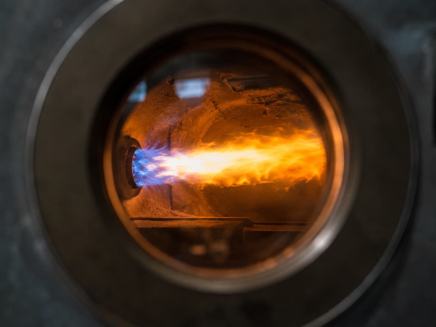
Burner fault codes come from the burner control box, not from the burner brand. Two models from the same manufacturer can carry a Siemens control box and a Honeywell one respectively — and their code tables are completely different. The first step in any correct diagnosis is to read the model number from the control box label: LME21.130, LMO24.255, DKG 972, LMV27.100, and so on.
Safety first: how many times can you press reset?
Two or three times consecutively at most. Every reset attempt makes the burner try to open fuel again. If ignition fails, a further quantity of unburnt fuel enters the combustion chamber on each attempt. Repeated resets are therefore a genuine explosion risk.
Also worth knowing:
- A safety lockout is retained in memory even after a power failure. Switching the supply off and on does not clear the fault; it only makes the record harder to read.
- If the same fault recurs quickly, stop resetting. A repeating lockout is not a coincidence — it is the signature of a degraded component.
- If there is a smell of gas in the plant room, do not operate any electrical equipment. Close the main gas valve, ventilate the space and call the gas emergency line.
Which control box is fitted? Brand-to-control-box mapping
The table below shows the pairings most often encountered in the field. The definitive answer is always the label on the control box — within a single brand, the control box varies by model and year of manufacture.
| Burner brand | Control boxes commonly encountered |
|---|---|
| Weishaupt | Siemens LME/LMO series; on larger units, Weishaupt's own W-FM 50/100/200 managers |
| Baltur | Siemens LME/LMO/LMV or Honeywell–Satronic, depending on model |
| Riello | Riello's own RMG/RMO series, or Siemens |
| Ecoflam, Cuenod, Elco | Predominantly Siemens and Honeywell–Satronic |
| Regional manufacturers | Siemens, Honeywell–Satronic or Brahma, depending on model |
This is why searching for a single "[brand] fault code table" is misleading. The right question is: which control box is fitted to this burner?
Siemens LME / LMO fault codes (red LED blink code)
On Siemens LME (gas) and LMO (oil) control boxes, faults are signalled by the number of repeated blinks of the red LED in the reset button. The LED flashes a set number of times, pauses briefly, then repeats the same sequence. Counting the blinks is the whole diagnosis.
| Blinks | Meaning | Most likely causes in the field |
|---|---|---|
| 2× | No flame established at end of safety time | Gas valve not opening, low gas pressure, ignition electrode gap or position out of spec, faulty ignition transformer or HT lead, contaminated ionisation probe, mixture too lean |
| 3× | Air pressure switch fault / no air pressure signal | Blocked or cracked impulse hose, dirty fan impeller, blocked air filter, incorrect switch setting or failed contact |
| 4× | Extraneous light at burner start-up | Leaking safety shut-off valve, damp flame detector, UV cell reading hot refractory glow as flame, leakage in detector wiring |
| 5× | Air pressure switch time supervision (contact stuck in working position) | Welded switch contact, hose on wrong port, chimney back pressure |
| 6× | Reserved / not used (model dependent) | — |
| 7× | Too many flame losses during operation | Unstable flame, fluctuating gas pressure, incorrect fuel–air ratio, chimney draught problem, marginal ionisation signal |
| 8× | Oil pre-heater time supervision | Failed heating element, faulty thermostat, high fuel viscosity |
| 10× | Wiring error or internal control box fault | Live and neutral reversed, missing earth, short on output contacts, failed control box |
| 14× | CPI / closed position indicator contact not closed (where fitted) | Valve position switch or valve proving system |
The most important distinction is between 2× and 4×. Both present as "it won't light", but the root causes differ: 2× lies in the fuel or ignition chain, while 4× can indicate a leaking valve. If 4× recurs, the plant should not be operated until a valve tightness test has been carried out.
Blink counts apply to common models in the LME/LMO family. Verify against the datasheet for the specific control box before commissioning; minor differences exist between sub-models.
Siemens LMV series (AZL display) fault codes
The LMV2x/LMV3x and LMV5x show an alphanumeric code on the AZL display rather than a single LED pattern. Two pieces of information appear:
- Error / Loc code: the main fault class
- Diagnostic code: the specific cause within that class
Both must be read together — the main code alone gives an incomplete picture. Several main codes follow the same logic as the LME family:
| Code | Meaning |
|---|---|
| 2 | No flame at end of safety time |
| 3 | Air pressure switch / air pressure fault |
| 4 | Extraneous light |
| 7 | Flame loss during operation |
The LMV3x and LMV5x add separate code groups for actuator position errors, fuel–air ratio control faults, O₂ trim faults and parameter/CRC errors. These must be read from the manufacturer's datasheet, and intervention should be left to an authorised service engineer: an incorrect parameter change on an LMV directly affects both the combustion setting and the safety functions.
Reading faults on Honeywell–Satronic control boxes
There is an important difference in this family: most TF, DKG, DKO and DMG series units have no blink code. There is a single red lockout lamp on the reset button, which tells you the unit has locked out but not why.
Diagnosis is therefore made by measurement:
- Measure the flame signal. A microammeter is connected in series between the control box and the ionisation probe.
- Check gas and air pressure switch contacts to follow the interlock chain step by step.
- Verify ignition transformer output and electrode gap.
- Confirm live/neutral orientation and earthing (see fault 2 below).
Newer digital models such as Honeywell's MMI series do provide LED-based diagnostic codes. Always confirm the code table against the manufacturer's datasheet for the exact model number on the label.
Brahma (CM, SM, TDG series) and Riello's own control boxes (RMG/RMO) also carry model-specific LED indication; on Riello units, holding the reset button for a few seconds typically starts a visual diagnostic sequence.
The 7 most common burner faults
These seven account for the large majority of service calls. For each: the symptom, the causes, and the correct approach.
1. No flame established at end of safety time
Symptom: the burner runs the fan, completes pre-purge, there is a brief click, and it locks out. 2× blinks on Siemens.
Causes:
- Gas pressure below the minimum threshold (regulator, blocked filter, undersized pipework, several appliances firing simultaneously)
- Burnt safety valve coil, or valve mechanically failing to open
- Ignition electrode gap, angle or height has drifted; cracked ceramic insulator
- Faulty ignition transformer or HT lead
- Mixture too lean at ignition position — too much air, mixture will not catch
- On oil: blocked or coked nozzle, low pump pressure, air in the fuel line
Correct approach: electrode gap and position must be set to the manufacturer's stated dimensions. "Roughly right" electrode setting is the single most frequent source of repeat call-outs.
2. Weak or absent ionisation (flame) signal
Symptom: the flame is visibly present but the burner still locks out — usually flame loss during operation (7× blinks) first, then full lockout.
Causes:
- Ionisation probe fouled with soot or oxide
- Cracked ceramic insulator, so the signal leaks to earth
- Poor or missing chassis earth
- Live and neutral reversed. Ionisation measurement is referenced to neutral; with the supply reversed the signal collapses even though the flame is present. This is the classic cause of "unexplained" faults appearing straight after other work on the panel.
- Distorted flame geometry — the probe is not properly immersed in the flame
- Excess air pushing the flame away from the probe
Correct approach: always measure the signal with a microammeter. Most control boxes require a minimum of around 1 µA; a healthy installation typically reads 4–8 µA (the exact threshold is stated in the datasheet). Thresholds for photocells and UV cells on oil burners are different.
3. Air pressure switch fault
Symptom: lockout after pre-purge, before ignition. 3× or 5× blinks on Siemens.
Causes:
- Impulse hose blocked, cracked or fitted to the wrong port
- Fan impeller and intake grille clogged with dust, reducing pressure
- Incorrect switch setting (adjusted by trial and error after previous work)
- Welded contact — this is what 5× blinks indicates
- Plant room fresh-air louvre closed or undersized, which is both common and dangerous
Correct approach: the switch setting is not arbitrary; it is derived from the fan pressure measured at commissioning. If the louvre is blocked, open the louvre — do not lower the switch setting to compensate.
4. Low gas pressure switch alarm
Symptom: the burner will not start at all, or drops out when it steps up to high fire.
Causes:
- Blocked gas filter
- Regulator out of adjustment or ruptured diaphragm
- Undersized pipework; multiple appliances drawing simultaneously
- Seasonal drop in network pressure
- Failed pressure switch
Correct approach: pressure must be measured with the burner running at high fire. Static pressure can look perfectly normal and still collapse under load.
5. Extraneous light
Symptom: the burner locks out before it starts. 4× blinks on Siemens.
Causes:
- Leaking safety shut-off valve with residual flame in the chamber — the critical scenario
- Hot refractory glow being read as flame by a UV cell or photocell
- Damp photocell or leakage in its wiring
- External light entering through the detector housing
Correct approach: test valve tightness first. If the detector is simply swapped out as "faulty" and a leaking valve is missed, the real hazard remains in place.
6. Fan motor and electrical faults
Symptom: the burner does not turn at all, runs noisily, or trips the overload.
Causes:
- Overload set incorrectly, or burnt contactor contacts
- Worn bearings causing vibration and noise
- Weak run capacitor on single-phase motors
- Phase loss on three-phase motors
- Dirt build-up on the impeller causing imbalance and raised current
Correct approach: measure motor current on all three phases and check for imbalance. A dirty impeller does not only raise current — it reduces air volume and therefore corrupts the combustion setting.
7. Flame loss during operation
Symptom: the burner lights normally, runs for a while, then locks out. 7× blinks on Siemens.
Causes:
- Fuel–air ratio at the margin, so the flame is unstable at high fire
- Insufficient or excessive chimney draught; wind-induced back pressure
- Gas pressure fluctuating under load
- Diffuser position shifted or fouled
- Marginal ionisation signal (assess together with fault 2)
- On oil: coked nozzle, water or sludge in the fuel
Correct approach: this fault is almost always diagnosed with a flue gas analyser. Any adjustment made without measuring O₂, CO and flue gas temperature across all firing rates is a temporary fix.
Which faults are urgent?
| Situation | Urgency | Action |
|---|---|---|
| Smell of gas | Emergency | Do not touch electrical equipment; close gas, ventilate, call the gas emergency line |
| Recurring extraneous light (4×) | Emergency | Do not operate the plant; carry out a valve tightness test |
| Lockouts repeating at short intervals | High | Stop resetting and call a service engineer |
| High CO in flue gas | High | Combustion adjustment and flue inspection |
| Single lockout, then normal operation | Medium | Log it; investigate at next service |
| Gradual efficiency loss, increasing soot | Planned | Address within scheduled maintenance |
The only way to stop faults recurring: planned maintenance
Most of the seven faults above do not appear suddenly. Electrode erosion, filter blockage, impeller fouling and pressure switch drift develop over months — efficiency degrades first, lockouts follow. For intervals and a full checklist see how often burner maintenance should be carried out, and for the underlying operating logic see what a burner is and how it works.
Safety notice: work on the gas train, ignition circuit and combustion settings must be carried out by trained and authorised technical personnel only. Unauthorised changes to control box parameters can disable safety functions.
Frequently Asked Questions
How do you read burner fault codes?
Fault codes are read from the burner control box rather than the burner brand. On the Siemens LME/LMO series the code is the number of repeated blinks of the red LED in the reset button. On the LMV series an alphanumeric error code and diagnostic code appear together on the AZL display. Classic Honeywell–Satronic models such as the TF and DKG have no code at all, so diagnosis is made by measurement.
What does 4 blinks mean on a Siemens LME?
Four blinks indicates extraneous light detected at burner start-up. The most serious possible cause is a leaking safety shut-off valve; a damp flame detector or the glow of hot refractory can also trigger it. Where 4 blinks recurs, the plant should not be run until valve tightness has been tested.
How many times can you press the burner reset button?
Two or three times consecutively at most. Each failed attempt admits a further quantity of unburnt fuel into the combustion chamber and increases explosion risk. If the fault recurs, call a qualified engineer rather than resetting again.
Why does the burner lock out when there is clearly a flame?
A lockout with a visible flame means the flame is not being detected. The most frequent causes are a fouled or cracked ionisation probe, poor earthing, reversed live and neutral connections, and excess air pushing the flame away from the probe. Diagnosis is made by measuring the flame signal with a microammeter.
Does a power cut reset a burner lockout?
No. A safety lockout is retained in the control box memory even with the supply removed. Switching the isolator off and on does not clear the fault — it only makes the stored information harder to read.
Is there a separate fault code table for each burner brand?
No, because the codes are generated by the control box fitted to the burner, not by the burner manufacturer. Different models from the same brand may carry Siemens, Honeywell or Brahma control boxes. The correct table is selected from the model number on the control box label. ---
About Beray Enerji
Beray Enerji is an Istanbul-based burner service company operating across Türkiye, with primary coverage in the Marmara, Thrace and Aegean regions. We provide fault diagnosis, repair, spare parts supply, commissioning and flue gas analysis for gas, oil and dual-fuel burners of all makes and models, backed by a technical team with 30 years of field experience. For 24/7 emergency response, contact us on +90 (000) 000 00 00 or at info@berayenerji.com.
Related services: Burner repair service · Burner maintenance · Contact
References
- EN 676 — Automatic forced draught burners for gaseous fuels
- EN 267 — Automatic forced draught burners for liquid fuels
- EN 161 / EN 1854 / EN 1643 — Gas valves, pressure sensing devices and valve proving systems
- Siemens burner control technical documentation (LME, LMO, LMV series)
- Honeywell–Satronic burner control technical documentation
- Brahma and Riello control box datasheets